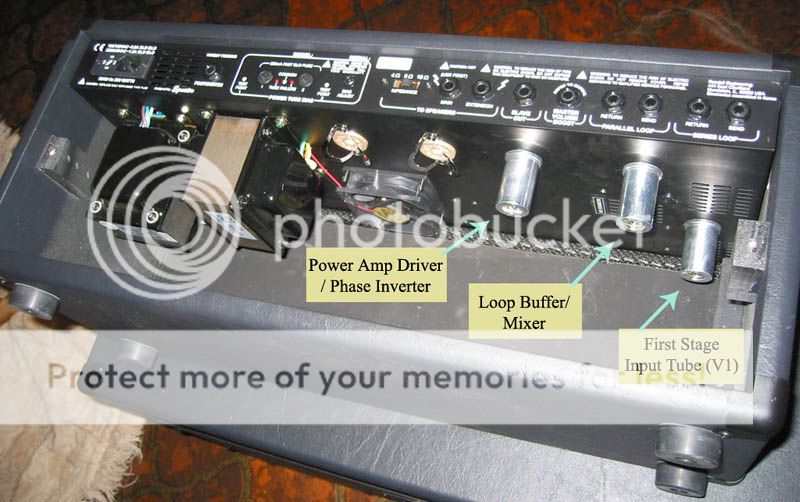
The mysterious V1...

Synergy/MTS Forum

Help Support Synergy/MTS Forum:

This site may earn a commission from merchant affiliate links, including eBay, Amazon, and others.
Had I ventured a guess I would say the V1 actually is a buffer as only 1/2 of it is used in the circuit. That would make sense - most amps use 1 or 2 valves for tone and/ or distortion and these are in the modules.

V2 is the phase inverter I believe (both sides are used in mono and before the master volume and loops) and V3 is the post-loop summing amp + output buffer. There is another thread on here with an illustration of the signal path through a Randall RM-4, which is similar to mine, where V2 and V3 are explained but not so the V1.
 
Now I'm wiser. The V1 in the rack is in deed the input valve, or one half of it (one triode) is - as is the case in any Fender or Marshall or what-have-you. The other half of it in an ordinary amp would have been used for the first gain stage, if there was any, or in the case of e.g. vintage Marshals taken care of the second input.

This puts us in a sort of dilemma: In a Fender tweed of Marshall we want this to be a harmonically rich and warm, maybe even dark valve - like the Mullard, Tung-sol or other. In a Fender blackface and similar we would want a 7025; a bright valve for a twangier tone.

The V2 in the amp... probably it's just a buffer of sorts. It doesn't appear to do any inverting. The triodes are not coupled similarly in parallell as would be the case with inverters. Also any inverting should be done just before the powervalves, no earlier than that.
 
joey_truelove said:
There is another thread on here with an illustration of the signal path through a Randall RM-4, which is similar to mine, where V2 and V3 are explained but not so the V1.

I remember that thread, but can't find it. Do you have a link? Thanks.
 
In old threads, I've heard it said that...

V1=input
V2=loop
V3=phase inverter

But it sounds like it is a more complicated than that. It'd be cool if Bruce would chime in.
 
I found this pic in the old HC MTS thread:

rm50hb.jpg
 
Something I picked up from Bruce Egnater, sometime when experience troubles with you MTS/RM amp you might have to change the V1..

Can't remember when or why :oops: , but I guees V1 works pretty hard..
 
Looking at the schematics of the RM100 acctually the V1 is one of the EL34's...

The first stage tube is V5 or V6....
 
Chad said:
joey_truelove said:
There is another thread on here with an illustration of the signal path through a Randall RM-4, which is similar to mine, where V2 and V3 are explained but not so the V1.

I remember that thread, but can't find it. Do you have a link? Thanks.
I found the website from where that was taken though. The Tone Of Life website obviously http://www.jaredcoberly.com/egnater/schematics/RM4_Signal_Path.jpg
 

Latest posts

Top